
Specifications
Current Rating |
N/A 2 A |
CKT |
N/A
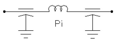 Pi |
Voltage (AC) |
N/A 250 V |
Voltage (DC) |
N/A 600 V |
Insertion Loss @ 0.15 MHz |
N/A 60 |
Body L |
N/A 2.87 in |
Body D |
N/A 1.25 in |
Terminal Dimensions A |
N/A 0.50 in |
Terminal Dimensions Thread |
N/A 7/16-20 |
Terminal Dimensions Z |
N/A 0.370 in |
Filter Circuit and Application Information
Filter Circuit and Application Information |
N/A
Three different types of filter circuits are shown in this series; L, Pi and T; each with its own characteristics An analysis of each application by engineering personnel will indicate a preferred circuit from cost, performance and size considerations, as directed below: Features:
Pi filters usually provide maximum "dB per dollar" in a matched 50 ohm system, but many times are less effective under actual operating or test conditions. They are particularly suspect in installations involving switching transients, since they can in some instances increase the interference problem rather than correct it. The T circuit is used primarily with switching circuits. It reduces noise level on the system lines, causes no deterioration in the life of switching contacts, and in some instances actually prolongs switch contacts life. The successful operation of any high frequency filter depends on adequate bonding and good RF isolation between input and output. The filter must be bonded to same potential as one side of the RF noise source being filtered. The performance of the filter can be completely masked by ineffective bonding or poor RF isolation between input and output circuits. The RF filter uses the case as common ground for the internal capacitor and cannot provide its total performance if RF is permitted to bypass the filters by means of coupling between input and output circuits. If you have any questions about the circuit to be employed, please call our engineering department for application advice and information. |