
| Items |
 A-6340 2.5 Amp Standard Model Tempest Filters |
A-6340A 2.5 Amp Standard Model Tempest Filters |
A-6345 5.0 Amp Standard Model Tempest Filters |
A-6345A 5.0 Amp Standard Model Tempest Filters |
A-6350 10.0 Amp Standard Model Tempest Filters |
|||||
| Voltage Rating | 120/230 VAC @ 60 Hz | |||||||||
| Visual/Mechanical | Per MIL-F-15733, Paragraph 4.6.1 | |||||||||
| Capacitance | Per MIL-STD-202, Method 305 @ 1 kHz | |||||||||
| Insulation Resistance | 1500 MΩ minimum per MIL-STD-202, Method 302 (prior to installation of bleeder resistors) | |||||||||
| Dielectric Withstanding Voltage | 1000 VDC line-to-line & line-to-chassis per MIL-STD-202, Method 301 | |||||||||
| Insertion Loss | Per MIL-STD 220 | |||||||||
| Voltage Drop | Less than 1% of rated voltage per paragraph 4.6.8 of MIL-F-15733 | |||||||||
| Terminal Strength | Per MIL-STD-202, method 211 | |||||||||
| Leakage Current | 5 mA maximum, measured per UL standard 1283 at 120 VAC, 60 Hz | |||||||||
| Voltage Discharge | Unit shall discharge to less than 30 VDC after removal or power | |||||||||
| Operating Temperature | -55 to +71 ºC | |||||||||
| Fig. |
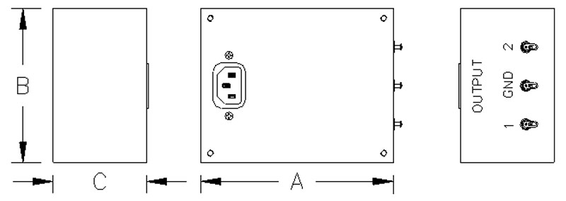 1 |
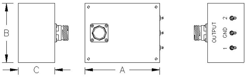 2 |
1 |
2 |
1 |
|||||
| Current Rating | 2.5 A | 2.5 A | 5 A | 5 A | 10 A | |||||
| Dimension A | 4.25 in | 4.25 in | 4.75 in | 4.75 in | 6.00 in | |||||
| Dimension B | 3.25 in | 3.25 in | 4.00 in | 4.00 in | 4.00 in | |||||
| Dimension C | 2.00 in | 2.00 in | 2.25 in | 2.25 in | 2.5 in | |||||
| Input Connection | IEC | J1 | IEC | J1 | IEC | |||||
| Output Connection | Solder Terminals | |||||||||
| Insertion Loss Curve |
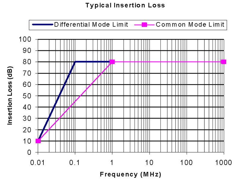 Insertion Loss Curve Figure 5 |
Insertion Loss Curve Figure 5 |
Insertion Loss Curve Figure 5 |
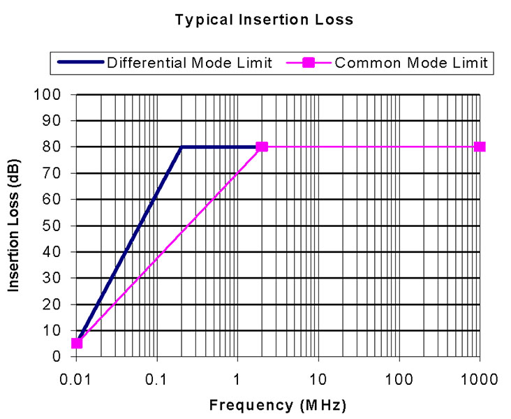 Insertion Loss Curve Figure 6 |
|||||
| Note | J1 is connector part number D38999/20WE6PN. | J1 is connector part number D38999/20WE6PN. | ||||||||
|
|
||||||||||